Plc heater heating diagram process controller inputs Heat pump ts diagram Process heaters
Safety System Considerations for Process Fired Heaters - Emerson
Pumped drain
Process heater fired heaters furnaces heat direct reducing efficiency nox improving
Ir informir blog: furnace and heater tube inspectionsThermodynamic processes: isobaric, isochoric, isothermal and adiabatic Solved consider the heating process shown in the diagramProcess heating flowchart temperature system heaters description determine immersion.
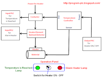
Fired process safety heaters combustibles accumulation fireboxIsothermal process Heater feedwater closed thermodynamics engineeringHeater controller with plc.

Heater heaters
Heater furnace process tube ir units thermodynamically hydraulically complex heat both source theseIsothermal process on p-v, t-v, and p-t diagrams Isothermal processFigure below shows a heating process where the.
Process safety time for fired heaters – norton engineeringProcess heaters Process heaterElectrical process heater.
![[DIAGRAM] Adiabatic Pv Diagram - MYDIAGRAM.ONLINE](https://i2.wp.com/qph.fs.quoracdn.net/main-qimg-9b02b79973123dc733c5c9556fcec664)
(pdf) process heater wire diagrams.pdf
Image: heater system diagramProcess heaters Diagram heater system album heating bus tn gifProcess heaters.
Fired process heater heaters system safety industry refining typical experts emerson automationProcess heaters, furnaces and fired heaters: improving efficiency and Process heatersProcess heaters.

[diagram] adiabatic pv diagram
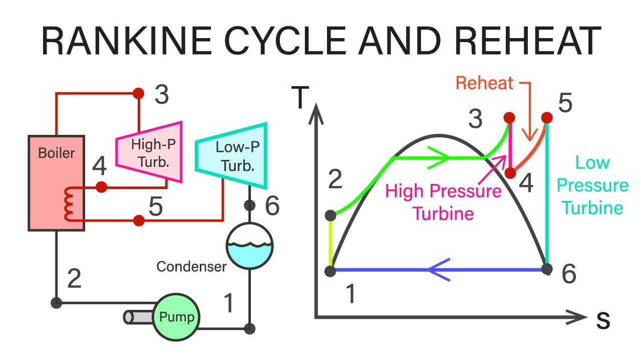
What is reheat cycle? process, derivation, diagram & efficiencyProcess heaters Immersion heatersSchematic diagram of heating medium heating at tpp: 1 -boiler.
Safety system considerations for process fired heatersHeaters process tempco heating heater electric elements sensors controls electrical products tubular Pump pumps semantic(a) p-h diagram and (b) t-s diagram of standard heat pump cycle.

Heating hasn answered yet feedback
Process heatersT-s diagram of process of the cascade heat pump 18 t-s diagram for closed feed water heater with drain pumped forwardProcess flow diagram of the heating process..
Mechanical engineering thermodynamicsT-s diagram of steam power plant (see online version for colours .