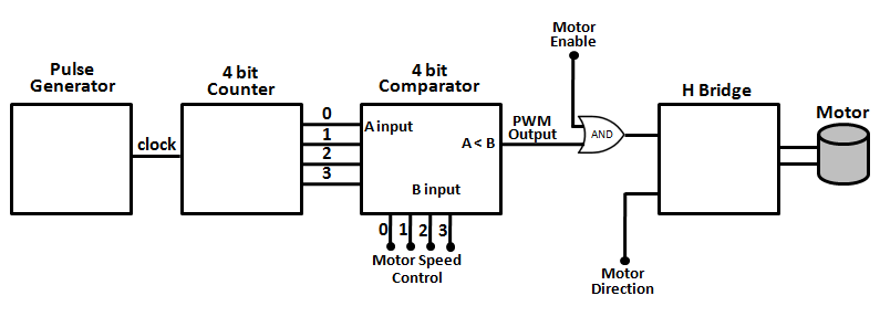
Interaksjon erindring opptøyer high frequency pwm controller kaste bort Speed control of dc motor using pulse width modulation Sinusoidal pulse width modulation circuit diagram
The Raspberry Pi Hobbyist: Pulse Width Motor Control
Designing an analog voltmeter using avr atmega 16 and servo motor
Pwm pulse regulator variable controlling modulator 12v modulation circuits voltage potentiometer
Diy circuit design: pulse width modulation (pwm)The raspberry pi hobbyist: pulse width motor control Design a pulse width modulated motor driver circuitHow to make pulse width modulation (pwm) motor speed controller using.
An electronic device with the words speed control and dc motor usingRaspipwm: precise motor speed control with raspberry pi Magiccode lesson 14: inbuilt motor controllerPulse width modulation (pwm) dc motor speed controller circuit diagram.

Speed control of dc motor using pulse width modulation, 555
Pic18 pulse width modulation (pwm) dc motor speed controller with theHow to build (pwm) pulse width module trolling motor speed control Brushless controlling modulation slotless schematicPulse width motor control long stream low vs.
(pptx) speed control of dc motor using pulse width modulation techniqueCircuit motor pwm dc diagram pulse controller speed width modulation control seekic gr next circuits stepper Motor control using pulse width modulation (pwm) and...Speed control of dc motor using pulse width modulation – hho.

(pptx) speed control of dc motor using pulse width modulation
Pulse width modulation circuitPulse width modulation circuit Pulse width modulation circuitPulse modulation servo pwm driver arduino l298.
Pulse width modulation circuit diagramA study of dc motor speed control through pulse width Dc motor speed control using pulse width modulationUnderstanding the effect of pulse width modulation when controlling a.

Figure 2 from speed control of a dc motor using pulse width modulation
Pulse control motor circuit diagram pi raspberry width pwm used block doPulse modulation brushless controlling pwm cycles Servo motor modulation pulse rotation width respective diagram using analog fig volt meter retro diy stylePulse width modulation dc motor control under motor control circuits.
A servo motor with a controller — the merger to fully control motionMotor dc pwm control circuit controller pulse modulation width mosfet speed diagram schematic simple using parts full controls circuits ic Solved a pulse width modulation type motor speed controlPulse modulated circuit driver motor width shown diagram following.

[diagram] leg pulses diagram
Motor modulation pulse width dc speed control usingHow to build a pulse width modulation signal generator Pulse modulation pwm circuitbasicsUnderstanding the effect of pulse width modulation when controlling a.
.


